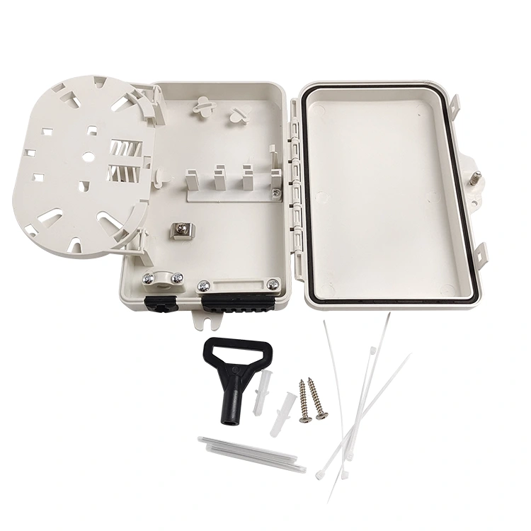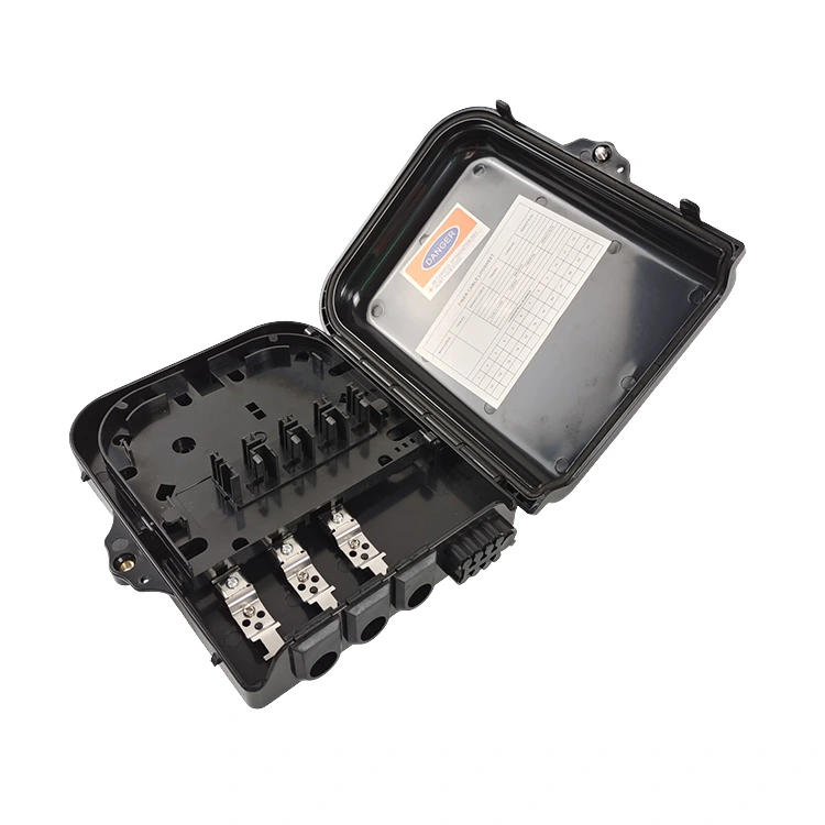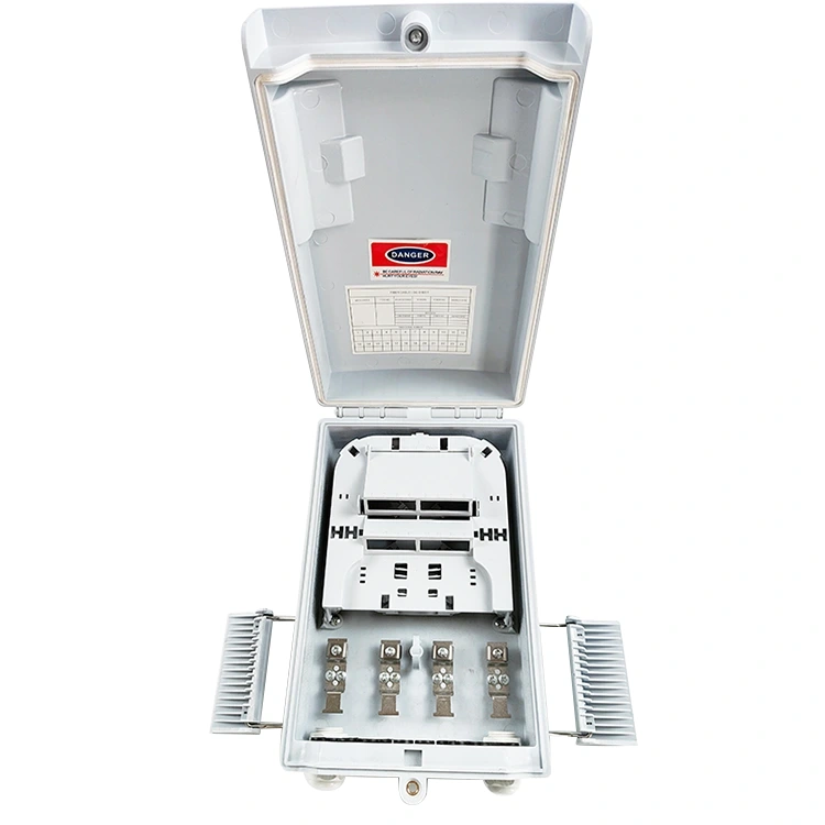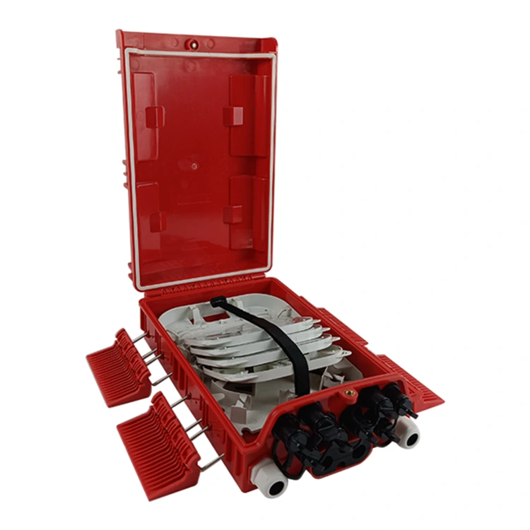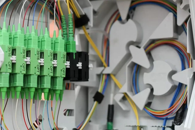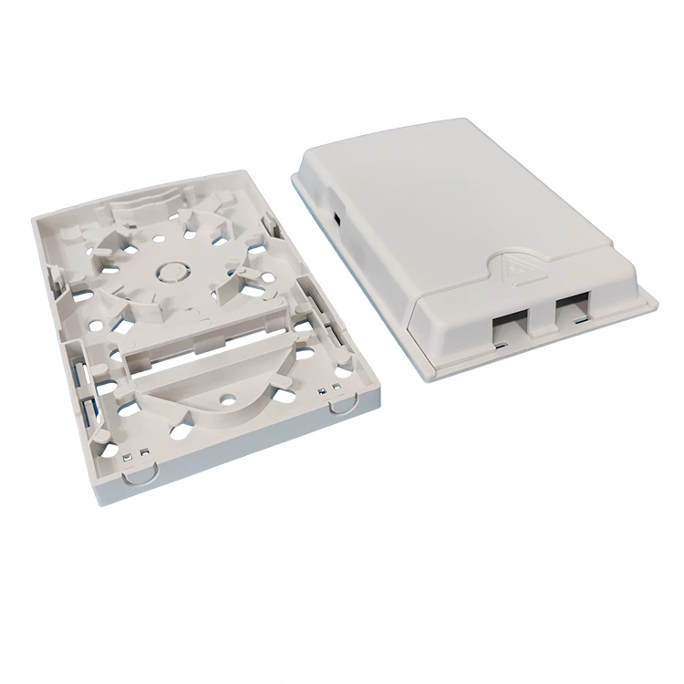

Fiber access networks require organized connection points to manage incoming optical cables and distribute fiber connections to multiple destinations. A distribution enclosure brings together important functions such as fiber termination, fusion splicing, optical splitting, adapter connections, and excess fiber management. Its capacity, internal layout, housing material, protection rating, and installation arrangement influence how effectively it fits an FTTH or FTTx deployment. Understanding these characteristics helps network planners, telecom contractors, installers, and equipment distributors select suitable configurations for residential buildings, commercial properties, outdoor access points, and expanding communication networks. From compact subscriber terminals to higher-capacity distribution units, the correct specification should match the actual network architecture and installation environment.
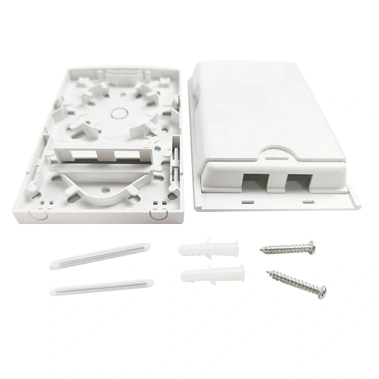
A Fiber Distribution Box is a passive network component designed to organize, connect, protect, and distribute fiber connections at an access point. It provides an interface between incoming feeder cables and outgoing distribution or subscriber drop cables. Depending on its construction and configuration, the enclosure can accommodate fiber splicing, adapter connections, PLC splitters, and additional fiber storage.
These enclosures are widely used in Fiber to the Home (FTTH) and broader Fiber to the X (FTTx) network architectures. They help establish organized connection points between the service provider's distribution infrastructure and the optical cables leading toward individual users, apartments, offices, and other premises.
A conventional optical distribution enclosure does not actively generate or amplify an optical signal. Instead, it provides a physical location where optical fibers can be terminated, joined, split, connected, and protected.
Its operation depends on passive optical components such as fiber adapters, pigtails, fusion splices, and PLC splitters. These components work together to establish the required optical connections without the enclosure itself requiring electrical power for signal processing.
This distinction is important when planning network architecture. Active equipment such as optical line terminals and subscriber-side optical network terminals performs functions that are different from the physical connection and distribution tasks handled by passive enclosures.
Distribution enclosures can be installed at different points between a service provider's central equipment and the final connection at a customer location. Their exact position depends on the network design, subscriber density, cable routes, and the chosen splitting arrangement.
In a residential project, an outdoor enclosure may connect a neighborhood distribution cable to individual building drop cables. In a commercial property, an indoor terminal can organize optical connections serving multiple offices, floors, or equipment areas.
The installation point should provide suitable environmental protection, convenient technician access, and enough internal space for the intended fiber connections.
FTTH networks extend optical fiber connections toward individual homes, while FTTx describes a broader group of architectures in which fiber reaches different points in the access network. Depending on the deployment, these points may include buildings, cabinets, distribution terminals, or individual customer premises.
A typical passive optical network contains several stages. The fiber distribution point connects different sections of the optical infrastructure and helps organize the transition between feeder and drop cables.
A simplified FTTH connection path may include the following components:
The position of the PLC splitter can vary according to the network topology. Some designs place the splitter inside a distribution enclosure, while other architectures use a separate splitting location. This affects the internal capacity and component arrangement required at each connection point.
A centralized splitting architecture places the optical splitter at a relatively centralized distribution point. From there, individual optical paths continue toward the intended subscribers.
This arrangement can make splitter identification and maintenance more straightforward when the distribution location is accessible. However, it also influences the number of outgoing fibers and the connection capacity needed at that point.
Distributed splitting uses multiple splitting stages at different locations in the access network. For example, an initial splitter may feed downstream terminals, where additional optical splitting serves individual subscribers.
This approach requires careful attention to splitter ratios, available optical power, connection losses, and the number of downstream branches. The selected enclosure must provide enough space for its intended function without unnecessarily combining network stages that are designed to remain separate.
Provides organized connection points for neighborhood distribution, residential buildings, apartment complexes, and individual subscriber drop cables.
Supports fiber distribution across office spaces, multi-floor buildings, commercial facilities, and shared communication infrastructure.
Helps operators manage feeder connections, branching points, optical interfaces, and subscriber access in FTTx deployments.
Organizes optical links between communication rooms, buildings, equipment areas, and selected industrial locations.
The network design should determine the location and function of each enclosure before equipment is selected. Understanding the optical path first makes it easier to identify the required cable entries, adapter positions, splitter capacity, and internal fiber management arrangement.
The internal layout determines how easily technicians can install, connect, inspect, and maintain optical fibers. Although enclosure designs differ, several functional elements are commonly involved in optical distribution applications.
The Fiber Distribution Box brings these elements together in an organized housing so that incoming and outgoing fiber routes can be managed without unnecessary interference.
Fiber splicing joins two optical fibers to establish a continuous optical path. Fusion splicing is commonly used in telecom installations because it creates a permanent connection between prepared fiber ends.
Inside a distribution enclosure, splice trays provide designated positions for organizing and protecting the completed splice points. They help prevent loose fibers from crossing other components or becoming exposed during routine maintenance.
The number of splice positions should correspond to the required cable arrangement and the intended network capacity. Sufficient space is also necessary for splice protectors and fiber routing.
Optical adapters provide mechanical interfaces between compatible connectors. Common interface options include SC, LC, and other connector formats, depending on the network and equipment requirements.
SC simplex adapters are commonly used in access-network applications. Their positioning inside the enclosure should make it possible to connect and disconnect compatible patch cords without unnecessary bending or tension.
Adapter configuration should also correspond to the required optical interface and connector polish. For example, SC/APC and SC/UPC should not be treated as interchangeable connection types simply because they use the same general connector family.
A Planar Lightwave Circuit (PLC) splitter divides an incoming optical signal into multiple output paths. Depending on the network design, split ratios such as 1:4, 1:8, 1:16, or 1:32 may be considered.
Splitter placement should allow technicians to access the component and manage its input and output fibers. The enclosure must accommodate the physical dimensions of the selected splitter module as well as the necessary routing space.
Incoming and outgoing cables need suitable fixation points so that external pulling forces are not transferred directly to delicate fiber connections.
Cable clamps, fastening structures, entry seals, and dedicated routing channels help organize the cable arrangement. Their suitability depends on the cable diameter, construction, entry method, and installation environment.
Optical fibers require controlled routing within the housing. Excess fiber should be stored in designated areas rather than compressed into random spaces.
Internal storage structures help maintain appropriate bend conditions, separate incoming and outgoing fibers, and make it easier to identify individual connections during inspection.
| Internal Component | Main Function | Selection Consideration |
|---|---|---|
| Splice Tray | Organizes and protects fusion splice points. | Number of splices and available tray positions. |
| Adapter Panel | Provides interfaces for compatible optical connectors. | Adapter count, connector type, and configuration. |
| PLC Splitter | Divides optical signals into multiple output paths. | Split ratio, module dimensions, and optical specifications. |
| Cable Clamp | Secures feeder and drop cables. | Cable diameter and required retention arrangement. |
| Fiber Storage Area | Organizes excess fiber and connection routing. | Fiber quantity, bend requirements, and maintenance access. |
| Sealing Structure | Helps protect cable entry and enclosure openings. | Installation environment and required IP protection. |
Capacity is one of the first specifications to evaluate when selecting an optical distribution enclosure. It determines how many connections can be organized within the equipment and how much room is available for future network changes.
Capacity labels such as 4-core, 8-core, 12-core, 16-core, and 48-core describe different product configurations. However, buyers should not assume that the core count, adapter count, and splitter output count always have a one-to-one relationship.
Core capacity relates to the number of optical fibers that the equipment is designed to accommodate in its intended arrangement. It should be considered alongside the number of fusion splices, outgoing connections, and available internal storage positions.
A network planner should identify the number of feeder fibers entering the enclosure and the number of downstream connections required. This establishes the basic capacity requirement before the physical product is selected.
Adapter count refers to the number of connector interfaces provided by the enclosure configuration. An enclosure may have several adapter positions, while the actual number of active connections depends on the splitter arrangement and network design.
The connector type and adapter configuration also need to match the patch cords and connected devices. An enclosure with a suitable number of ports can still be unsuitable if its connector interfaces do not match the intended network.
Different enclosure designs are available for different FTTx applications. The following examples illustrate how capacity, adapter arrangements, materials, and dimensions can vary between individual models.
| Model | Core / Adapter Configuration | Splitter Arrangement | Housing / Protection | Dimensions (mm) |
|---|---|---|---|---|
| YY-H001 | 8 cores / 8 waterproof adapters | 1:4 or 1:8 mini PLC | ABS / IP65 | 320 × 220 × 95 |
| YY-H002 | 16 cores / 16 waterproof adapters | 1:8 or 1:16 mini PLC | ABS / IP65 | 320 × 214 × 133 |
| YY-H007 | 8/9 cores / 11 waterproof adapters | 1:8 mini PLC | ABS / IP68 | 195 × 200 × 80 |
| YY-H009 | 8 cores / 8 adapters | 1:8 mini PLC | ABS / IP65 | 300 × 210 × 90 |
| YY-H037 | 16 SC simplex adapters | 2 × 1:8 or 1 × 1:16 PLC | ABS / IP65 | 285 × 190 × 100 |
These are model-specific examples, not universal specifications for every enclosure. A product drawing and technical datasheet should be checked to confirm the exact combination of splice capacity, adapter positions, cable entries, and splitter accommodation.
Choosing capacity only according to the number of connections currently required may leave limited room for later changes. Where network growth is expected, planners should consider the anticipated number of additional subscribers, spare cable positions, and whether the enclosure allows additional adapters or splitter modules.
However, an unnecessarily large enclosure can also create installation challenges where space is limited. The goal is to match capacity with the deployment plan while maintaining convenient access and effective internal cable organization.
Optical splitting is a central function in many passive FTTH network architectures. A PLC splitter distributes an optical input signal across multiple output paths, allowing one feeder connection to serve several downstream endpoints.
The splitter ratio determines how many output branches are created and influences the optical power available at each branch. It therefore needs to be considered as part of the complete optical link budget rather than as an isolated product feature.
| Splitter Ratio | Optical Output Paths | Typical Planning Consideration |
|---|---|---|
| 1:4 | 4 | Smaller distribution groups with fewer downstream connections. |
| 1:8 | 8 | Compact multi-subscriber distribution points. |
| 1:16 | 16 | Higher subscriber density within a defined distribution area. |
| 1:32 | 32 | Higher branch counts requiring careful optical budget planning. |
The table illustrates common split ratios, not a statement that every enclosure supports all four options. Physical compatibility must be checked against the product's splitter holder and internal layout.
Uniform splitters divide optical power across output paths according to a specified equal distribution. They are commonly used where the network architecture requires comparable optical distribution to several branches.
Non-uniform splitters allocate different portions of optical power to different outputs. These components can support cascaded network designs in which one portion continues toward downstream distribution points while another portion serves a local subscriber group.
For example, a network may use an unequal split arrangement to distribute optical power between a downstream terminal and local customer connections. The exact ratio should be determined through network planning and supported by the splitter's technical specification.
Every optical connection introduces some optical loss. Splitters, adapters, connectors, and fusion splices all contribute to the overall optical link budget.
When evaluating an enclosure, it is important to review the specifications of the installed optical components rather than attributing all optical performance characteristics to the plastic housing.
Connector compatibility also matters. SC/APC and SC/UPC interfaces require the appropriate corresponding connection components. Mixing incompatible connector-polish types can lead to poor connection performance and may damage connector end faces.
Splitter modules should be installed in designated positions and secured according to the enclosure design. Input and output fibers should follow their intended routing channels so they do not interfere with splice trays, adapters, or the closing mechanism.
A practical internal layout allows technicians to identify splitter connections without disturbing unrelated fibers. This is particularly useful when a distribution point serves several subscribers or supports staged network expansion.
The housing protects internal optical components and provides the physical structure for cable entry, closure, mounting, and maintenance access. Material selection and enclosure sealing should correspond to the environment in which the equipment will be installed.
ABS is widely used in communication equipment enclosures because it can be molded into practical shapes with integrated fastening points, cable pathways, and internal component supports. It is used in several outdoor enclosure configurations.
Other designs may use PP, PP with glass-fiber reinforcement, PC, or combinations of suitable engineering plastics. Each material has different characteristics in terms of impact behavior, rigidity, molding requirements, temperature response, and environmental resistance.
Buyers should review the specified housing material for the actual product model. A material used in one configuration should not automatically be assumed to apply to the entire product range.
The Ingress Protection (IP) rating indicates the degree of protection provided by an enclosure against solid-object ingress and water ingress under defined test conditions. The first digit relates to protection against solid particles, while the second relates to water ingress.
Different models may have IP55, IP65, IP67, or IP68 ratings, depending on their construction and intended installation environment. These ratings are not interchangeable and should be interpreted according to the applicable test requirements.
| IP Rating | Solid Protection | Water Protection | Selection Consideration |
|---|---|---|---|
| IP55 | Dust-protected | Protection against water jets under specified conditions. | Check installation exposure and the product's test specification. |
| IP65 | Dust-tight | Protection against water jets under specified conditions. | Suitable for applications requiring dust-tight enclosure protection. |
| IP67 | Dust-tight | Protection against temporary immersion under specified conditions. | Review immersion depth and test duration. |
| IP68 | Dust-tight | Protection against continuous immersion under conditions specified by the manufacturer. | Confirm the applicable immersion conditions and product declaration. |
The IP rating describes enclosure protection under defined conditions. It should not be interpreted as a complete guarantee against every environmental problem, including long-term UV exposure, corrosion of unrelated fittings, chemical exposure, or incorrect cable installation.
Outdoor installations may experience changing temperatures, humidity, rainfall, sunlight, and other environmental stresses. The material and sealing arrangement need to be suitable for the intended location.
For example, the YY-H037 model specifies an operating temperature range of -40°C to +85°C. This is a model-specific technical parameter and should not be applied to other product configurations without checking their individual datasheets.
Cable entry seals, housing joints, fastening structures, and the closing mechanism should also be evaluated together. Even an enclosure with a suitable rated housing may not maintain its intended protection if cable entries are installed incorrectly or damaged during operation.
Outdoor plastic enclosures should be evaluated for their intended exposure to sunlight and weather. UV resistance depends on the material formulation and manufacturing specifications rather than simply on the appearance of the housing.
For installations in exposed locations, confirm the manufacturer's environmental suitability information, installation instructions, and any applicable material or ageing test documentation.
Installation location determines several practical requirements, including enclosure dimensions, cable entry arrangements, mounting hardware, sealing structure, and technician accessibility.
Indoor enclosures are commonly used in communication rooms, building entrances, equipment spaces, floor distribution areas, and other controlled environments.
Since they are generally installed in less exposed locations, their selection may place greater emphasis on compact dimensions, organized internal connections, mounting convenience, and accessibility for technicians.
Wall-mounted designs can help keep optical cables organized while maintaining a designated service point. The mounting location should allow sufficient space to open the housing and access internal components.
Outdoor enclosures may be installed on building exteriors, access poles, distribution structures, or other suitable locations within the network. They need to accommodate environmental exposure and provide appropriate protection for internal optical connections.
Housing sealing, cable entry design, mounting strength, UV suitability, and the applicable IP rating should all be considered before installation.
Wall mounting provides a fixed installation point and is often suitable for building façades, communication areas, or designated outdoor service locations.
The wall surface should support the complete installed assembly. Cable routing should avoid sharp bends, excessive tension, and unnecessary exposure to mechanical damage. The enclosure should also remain accessible for inspection and maintenance.
Pole-mounted installations can place optical distribution equipment close to aerial cable routes and neighborhood access points. They are useful where the network design requires a distribution location on existing or purpose-installed poles.
Mounting brackets, fastening straps, enclosure weight, pole dimensions, and cable entry direction should be checked before installation. The equipment must be secured without deforming the housing or creating excessive stress at the mounting points.
Choosing a waterproof enclosure alone does not resolve every outdoor installation requirement. Cable glands, connectors, mounting hardware, sealing components, and installation workmanship all contribute to the protection of the completed assembly.
An organized internal structure is essential for long-term optical network maintenance. Technicians may need to identify a particular subscriber connection, inspect a splice, replace an adapter, check a splitter, or modify a downstream route.
These tasks become more difficult when fibers are crowded, poorly labeled, or routed through unrelated components. A practical internal arrangement helps reduce unnecessary handling and makes individual connections easier to locate.
Optical fibers should be routed in accordance with their specified minimum bend radius. Excessive bending can introduce additional optical loss or cause physical damage, depending on the fiber type and operating conditions.
Internal guides and storage channels should support smooth fiber paths rather than forcing fibers into tight loops. Fiber slack should be stored neatly without being compressed under the splice tray or enclosure cover.
Feeder cables, distribution cables, pigtails, splitter inputs, and splitter outputs should follow an understandable arrangement. Dedicated routing channels can help prevent tangling and reduce the likelihood of disturbing unrelated connections during maintenance.
A clearly organized layout is particularly important when an enclosure serves multiple subscribers or combines splicing, splitting, and adapter connections.
Identification labels help technicians associate optical ports with the correct subscriber, building, cable route, or downstream terminal. The specific labeling method may vary by operator or project, but consistency is essential.
Connection records should correspond to the physical layout. When a fiber is moved, a splitter is replaced, or an additional subscriber is connected, the relevant documentation should be updated.
An enclosure should allow the technician to access its intended components without unnecessary disturbance to other connections. Hinged trays, accessible adapter panels, suitable cable fixing points, and organized storage areas can all contribute to practical maintenance.
Before maintenance begins, the technician should identify the relevant optical path and follow the network operator's procedures. Optical fibers should never be viewed directly at their end faces because invisible laser radiation may be present.
Maintenance consideration: Keep splice trays, adapters, and splitter modules identifiable and accessible. Good cable organization helps reduce accidental disconnections and simplifies future network changes.
Choosing a suitable Fiber Distribution Box requires more than comparing port counts or selecting the enclosure with the highest protection rating. The product must match the optical network design, installation location, cable arrangement, and maintenance requirements.
Determine whether the equipment will serve residential FTTH, a multi-dwelling building, a commercial facility, a campus network, or another FTTx deployment.
The location of the equipment within the optical access architecture should also be clear. A subscriber access point may need a different configuration from an enclosure used for feeder cable splicing or a larger distribution point.
Identify the number of incoming fibers, required outgoing connections, intended splice positions, and expected subscribers. Consider whether the network will expand and whether additional adapter or splitter positions may be needed later.
Avoid selecting a product based on the core number alone. Review its internal arrangement and verify that the actual splitter and adapter configuration supports the intended design.
Identify the required connector interface, splitter type, splitting ratio, and fiber specification. Check the optical components' technical parameters and make sure they are compatible with the network's link budget.
Where pre-connected or pre-terminated solutions are planned, confirm connector types, cable lengths, interface designs, and compatibility with the downstream equipment.
Determine the enclosure's installation position and review the required housing material, IP protection, cable sealing, and operating temperature range.
Wall-mounted and pole-mounted designs may require different external mounting arrangements. Cable entry methods should also suit the actual cable diameter and installation route.
Review the enclosure's physical dimensions, splice tray arrangement, adapter placement, splitter holder, and available fiber storage. Confirm that the technician can perform the intended installation and maintenance tasks after all components have been installed.
| Selection Factor | Information to Confirm | Why It Matters |
|---|---|---|
| Application | FTTH, FTTx, residential, commercial, or campus network. | Defines the equipment's role in the network. |
| Fiber Capacity | Core count, splice positions, and subscriber requirements. | Ensures the physical configuration matches the connection plan. |
| Adapter Interface | SC, LC, UPC, APC, and adapter quantity. | Maintains connector compatibility. |
| Splitter Configuration | PLC type, split ratio, and module dimensions. | Supports the intended optical distribution architecture. |
| Housing Material | ABS, PP, PP+GF, PC, or specified material combination. | Matches the enclosure construction to the application. |
| IP Protection | Required ingress protection rating and test conditions. | Addresses dust and water exposure. |
| Installation | Indoor, outdoor, wall-mount, or pole-mount arrangement. | Ensures the enclosure and mounting accessories are compatible. |
| Maintenance | Tray access, cable routing, closure design, and labeling. | Supports inspection and future network changes. |
Before requesting a product configuration, network planners can prepare a specification containing the application, required capacity, cable details, connector type, splitter arrangement, installation environment, and mounting method.
Drawings and photos of the installation location can help clarify space limitations and cable entry requirements. Where an existing enclosure is being replaced, its dimensions and internal arrangement can also be used as a comparison point.
A clearly defined specification makes it easier to evaluate different configurations and confirm whether the selected equipment is suitable for the actual network design.
The following questions address common technical and purchasing considerations for optical network distribution equipment.
Its main function is to provide an organized and protected location for connecting incoming and outgoing optical fibers. Depending on the configuration, it can support fusion splicing, adapter connections, PLC splitters, cable fixation, and fiber storage within an FTTH or FTTx network.
A distribution enclosure generally provides subscriber-facing connection and distribution functions, often including adapters and optional splitters. A splice closure primarily protects cable joints and splice points along an optical cable route. Some products combine several functions, so the actual internal configuration and intended installation should be checked.
The main distinction is the intended fiber capacity and associated internal arrangement. A 16-core configuration can accommodate a different connection requirement from an 8-core design. However, the number of adapters, splice positions, and splitter outputs should be checked separately because these specifications are not necessarily identical.
ABS, PP, PC, and reinforced plastic materials are used in different communication enclosure designs. Suitability depends on the material specification, construction, environmental exposure, sealing arrangement, and intended service conditions. The technical documentation for the actual model should guide selection.
IP65 indicates that the enclosure is dust-tight and provides protection against water jets under specified test conditions. It does not mean the product is designed for continuous immersion. Cable entries, sealing components, and installation workmanship also influence the protection of the completed assembly.
Some configurations include designated positions for PLC splitter modules, such as 1:4, 1:8, or 1:16 arrangements. The supported splitter type, module size, and internal mounting position vary by model. Compatibility should be confirmed through the product specification.
Both are SC connector interfaces, but they use different ferrule end-face polishing designs. APC connectors have an angled end face, while UPC connectors have an ultra-polished end face. Their interfaces should be matched correctly throughout the optical connection to avoid compatibility and performance problems.
Some models are designed for combined indoor and outdoor applications, while others are intended for a more specific environment. The decision should be based on the manufacturer's application description, IP rating, operating conditions, cable entry design, and mounting requirements.
Incoming fibers, splice points, splitter connections, and outgoing fibers should follow designated routing channels. Fibers need suitable bend conditions and secure storage, while splice trays and adapter panels should remain accessible for maintenance. Connection labels should correspond to the network documentation.
Important details include the application, fiber capacity, adapter quantity, connector type, splitter configuration, feeder and drop cable dimensions, housing material, IP rating, installation method, and overall enclosure dimensions. Drawings or photos of the installation environment can help confirm the required configuration.
A conventional passive optical distribution enclosure does not require electrical power for its fiber connection, splicing, or passive splitting functions. It organizes passive components within the optical access network. Separate active network devices have their own power and equipment requirements.
Selecting optical distribution equipment requires a clear understanding of the network architecture and the conditions at the installation location. Core capacity, adapter configuration, PLC splitter compatibility, splice management, cable routing, housing material, and ingress protection all contribute to the suitability of the final configuration.
A well-planned distribution point provides organized connections between feeder and drop cables while protecting internal optical components and allowing technicians to carry out installation and maintenance tasks. The enclosure should also accommodate the intended subscriber connections without creating unnecessary restrictions on fiber storage or access.
Ultimately, choosing the right distribution enclosure means matching its technical specifications to the actual FTTH or FTTx deployment. Clear network planning, compatible optical components, suitable environmental protection, and careful installation work together to support an organized and maintainable fiber access network.
Planning an FTTH or FTTx deployment and looking for suitable optical distribution equipment? Explore Yuanyi company information and discuss your required fiber capacity, adapter configuration, PLC splitter arrangement, housing material, IP protection, and installation method with our team. Contact us to discuss your project requirements and find a suitable optical fiber distribution solution.
Send an Inquiry-